News:

SMF - Just Installed!

Main Menu
Menu

Show posts

This section allows you to view all posts made by this member. Note that you can only see posts made in areas you currently have access to.

Show posts Menu

Messages - paulsoulsby

#181
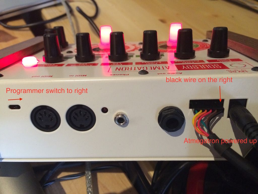
Can I check these 3 things first, before going further.
#182
Actually that's a rubbish suggestion, as we know that the problem is the shorted pins!

Let me have a bit more of a think about this....
#183
Hmm, do you have another Arduino, just to rule that out?  Doesn't need to be MIDI hacked.  Just needs to be Uno or Uno clone.
#184
7 is ground. 
1 is Value -.
5,6 are Function +/- as already mentioned.

Yes, these all should be tied together to ground when unpressed, but... through 10k resistors, way more than 15 ohms!  I'm pretty sure that this is the issue.

It might be worth checking that all the resistors are in the right places:


Also can I double check you were testing this with the shield out of the Arduino? 
#185
I've just stuck the schematic on the downloads page too, which may help. http://soulsbysynths.com/wp-content/uploads/2015/08/miniAtmegatron-PCB.pdf
#186
Yes that's correct (pins 0-7 on CONN1, so 12-13 would be 5-6 on CONN2).


#187
Hmm, this is a tricky.

The flashing is related to patch save, however it's Function - that should do this, not Function +.  There's nothing in the code at all to make the LED flash with the Function + button!

There's something clearly wrong in the area of these 2 switches, although it's hard to tell what off the top of my head.  You may need a multimeter / continuity tester to work this out. 

Function - (SW2) is connected to D13 on the Arduino
Function + (SW3) is connected to D12 on the Arduino

Can you test these connections with a multimeter (i.e. push the button and see if the connection is made).

Also, is there are short between D12 and D13 on the header?

Let me know if you need me to go into more detail about this.
#188
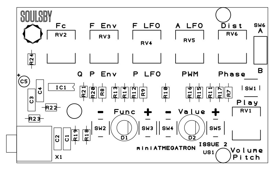
So the left LED is RGB, the right LED is RGB, but only uses red and green (no blue).

Here's the PCB layout.


If you think that 1 LED colour isn't working, double check that the solder pads aren't soldered together.  You can also test this with a multimeter - check all combinations of pads and make sure none are connected.
Paul
#189
Hi,

Here's the quick answer:
      PITCH LFO = 1,
      FILTER ENVELOPE = 16,
      DISTORTION = 17,
      FILTER CUTOFF = 74,
      FILTER RESONANCE = 71,
      LFO CLOCK DIV = 79,
      PWM = 91,
      AMPLITUDE LFO = 92,
      FILTER LFO = 93,
      PITCH ENV = 94,
      PHASER = 95,
      ALL NOTES OFF = 123

I'll do a proper MIDI table next week, along with other lookup tables.

Paul
#190
The Librarian software uses SysEx to communicate.  This requires both the MIDI In and MIDI Out to be connected, so the Atmegatron can "handshake" with the Librarian.

Although technically possible, it would be very difficult to transfer either User Waves or Memory Banks to anything other than the Librarian.  However transferring single patches is easy.

To transfer a patch from the Atmegatron to your DAW:  set the MIDI track in the DAW recording, or if it has a special SysEx editor, set it to receive.  Then select Amplitude Attack on the Atmegatron and press and hold the function knob for at least 2 seconds.  Your DAW should receive the Sysex Data.

To transfer a patch from your DAW to the Atmegatron: Select Amplitude Decay on the Atmegatron and press the function knob, so it goes green.  Then either play the MIDI track in your DAW or press transmit if it has a special SysEx Editor.  Your Atmegatron will receive and load the patch.
#191
Yeah sure, stackable headers will be fine. That would be a good way to add MIDI ports to it in fact.
The only downside would be that it wouldn't fit into the enclosure (when it becomes available).  But if you're using it more for experimentation, you probably won't want it in an enclosure anyway.
Just make sure you get long headers, so that the shield clears the USB port.
Paul
#192
Software announcement / Downloads page overhauled
August 27, 2015, 02:57:46 PM
The downloads page has now been overhauled and features V2 of the software.
Atmegatron users with software versions 1.0-1.4 (i.e. serial numbers < 1000), should install the EEPROM converter before installing the new software.
Atmegatron users with serial numbers > 1000 only need to install this software if they would like to return their Atmegatron to standard software after experimenting with other software versions.
#193
The Atmegatron is back on sale in the shop. There are some key differences to the new batch (i.e. serial numbers 1000 onwards):

  • Preloaded with V2 software
  • Slightly different enclosure colour and side panels
  • Knobs have indent instead of marker line
  • Programmer switch brought slightly forward
  • Shade of green of bank switch now matches the rotary encoders (very important)
  • Updated manual
#194
Cool, that's good news!  There's protection for reverse polarity and PSUs up to 24V, so it's pretty robust.  Anything over 24V and smoke may start to appear though!
#195
Hi,
Yes that's correct.  You can get suitable ones from most electronics shops and online.  The full spec is:
12V, 2A (or greater - def not less), 2.1mm DC plug, centre positive.

Paul